Product Description
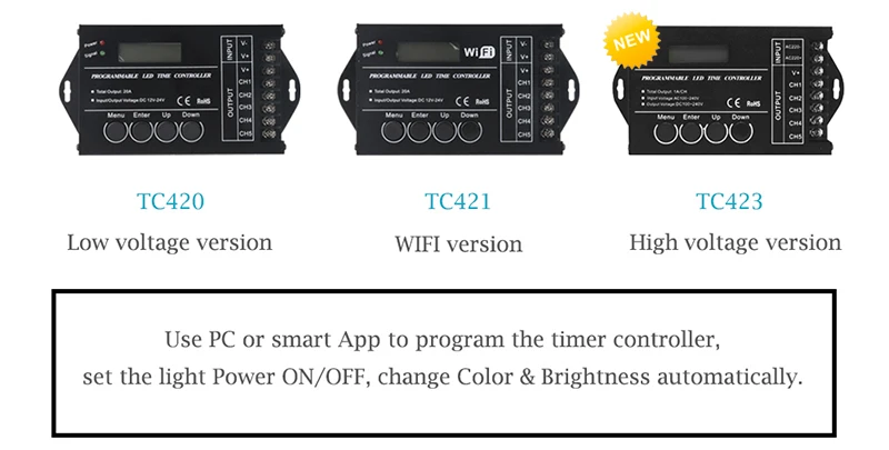
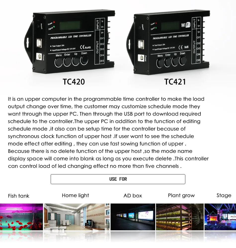
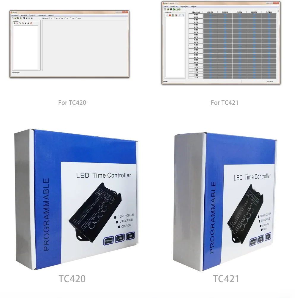
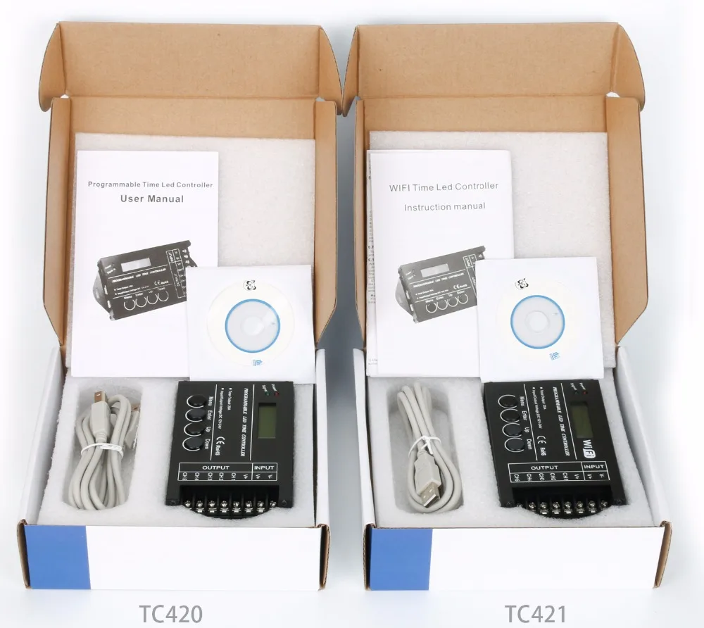
There is an upper computer in the WiFi TC421 programmable time controller to make the load output change over time, the customer may customize schedule mode they want through the upper PC or APP client. Then through the USB port or wifi to download required schedule to the controller.The upper PC and Mobile phone APP to the client in addition to the function of editing schedule mode ,it also can be setup time for the controller because of synchronous clock function of upper host .If user want to see the schedule mode effect after editing , they can use fast sowing function of upper . Because there is no delete function of the upper host ,so the mode name display space will come into blank as long as you execute delete .This controller can control load of led changing effect no more than five channels .And it can be used in the occasion of the plant lights, light box advertising, the stage, home decoration, etc.
Technical Parameter
product name:programmable time led controller
Working temperature: -20-60degree
Supply voltage: DC12~24V
Static power consumption: < 0.5W
External dimension: 150MM*78.5MM*26MM
Packing size: 185MM*180MM*54.8MM
Output: 5 channels
Maximum output current: 20A
Package Content
1*Programmable LED time controller
1*USB data cord
1*CD burned with compatible software
1*user manual

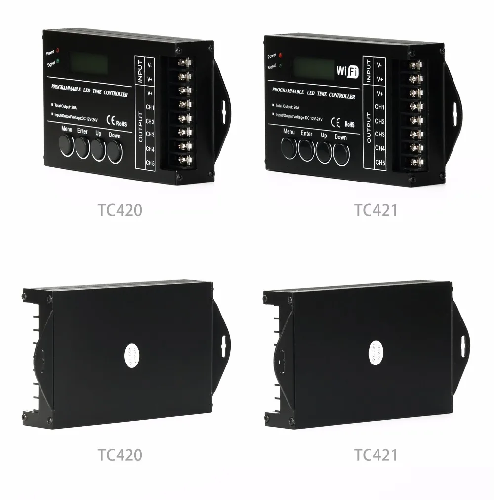
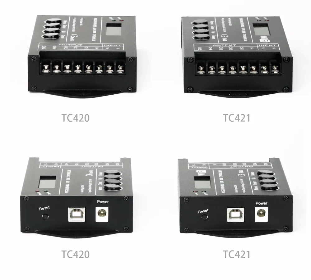


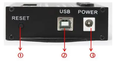
①RESET:For the reset key, when the controller is dead, it can touch the key to the reposition, only for the chip reset, not the initialization reset.
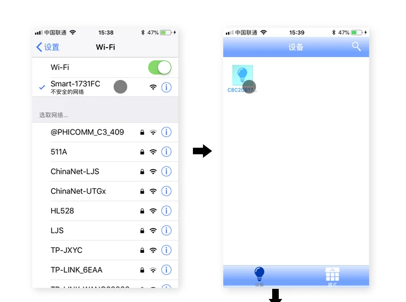
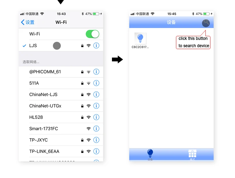
For TC421, if you connect the network of your own router, please long press menu key to reset to AP mode, and try to connect again, thanks.
②USB:It is USB signal joint entrance, when epistatic machine model after editing, can through the USB line to download to the controller.
③POWER:It is DC plug, when the load power is small, can choose this port to input voltage.
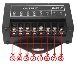
① CH1: It is the load output first channel negative pole;
② CH2: It is the load output second channel negative pole;
③ CH3: It is the load output third channel negative pole;
④ CH4: It is the load output 4th channel negative pole;
⑤ CH5: It is the load output 5th channel negative pole;
⑥ V+: It is the load output positive pole;
⑦⑧V+.V-: It is power supply input positive and negative pole, when the load power is too large, you can choose this 2 port.
(Remark: you only need to choose one between power supply input DC port and this ⑦⑧port , and don't connect the two input way at the same time!)
How to add TC421 to your local WiFi network:
